New Helm-mounted VHF Radio
--Blogpost written by Bob
One of the problems we encountered during our month-long sailing trip involved radio communications with marinas--several times we could not hail them on our handheld VHF from the cockpit because it is limited to only 1 and 5 watts of power. (Our primary VHF is located in the navigation station below and not accessible from the helm.)
In the unlikely event of another lightning strike (we already had one 3 years ago that knocked out all of our electronics) or, worse yet, being dismasted, a second (totally independent) radio system at the helm should still be operable and will provide an extra level of safety and security.
In the Bahamas, a VHF radio is used like a "party line" where a morning cruiser's net makes a weather forecast and announcements about the day's activities.
The Radio
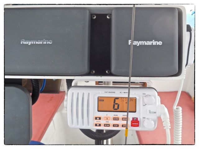
We purchased a new 25-watt ICOM IC-M412 Waterproof VHF transceiver for mounting at the helm--this is the same model we have below at the navigation station (but in black). Since we occasionally get splashed with salt water in the cockpit, this "waterproof" feature is very important.
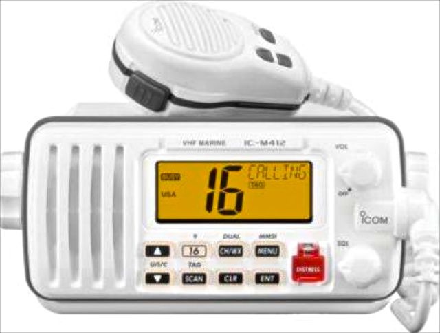 |
| I've always had a preference for ICOM-brand radio equipment and this model in white is very attractive as radios go. |
I mounted the radio on the underside of the instrument pod on the starboard side. (The chart plotter is in the same position on the port side.)
The Antenna
We decided to use a very small antenna made by GAM Electronics (Model SS-2) and mount it near the helm and very close to the radio. We purchased this locally--at Fawcett Boat Supplies.
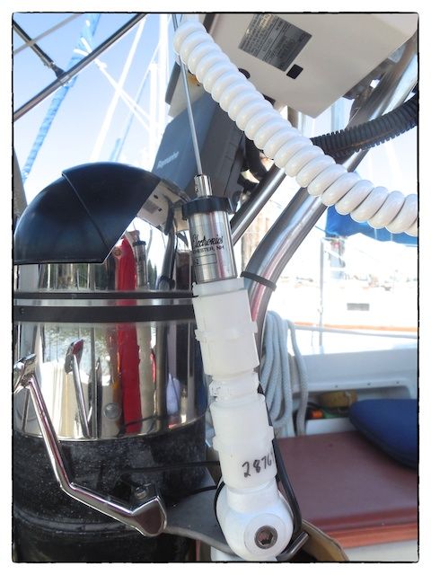
Since the antenna is about 36 inches high and I wanted to keep the antenna cable routing as simple as possible, I mounted the antenna on the pedestal on the starboard side just forward of the throttle controls. I used a Forespar Railfast nylon antenna mount--this mount has 1-14 male threads (which means 1" diameter and 14 threads per inch). The base of the antenna has 5/8-24 male threads and a very shallow nut (intended for fastening through an L-shaped mounting bracket).
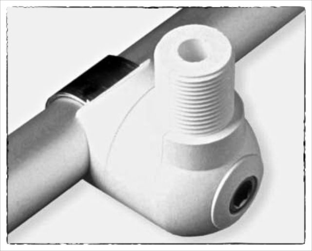 |
| Forespar's Railfast Nylon Antenna Mount is a handy way to mount the antenna on the pedestal. |
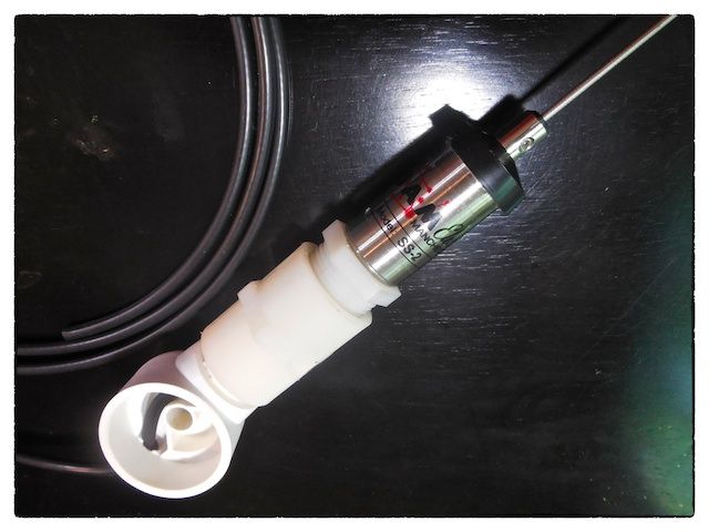 |
| The antenna assembly, with nylon plug adaptor, nylon coupling and part of antenna mount. |
I bought a 1-inch nylon coupling and a 1-inch nylon plug to make a mounting adaptor. The nylon coupling easily mounted to the Forespar antenna mount but I had to have an adaptor made out of the nylon plug--it had to have a 5/8-inch diameter hole through the center and then be bored out with an internal shoulder so that the shallow nut could be inserted to rigidly fasten the antenna. (I had to grind down the corners of the shallow nut to make this work as planned.)
The Completely Installed System
The most time-consuming part of this project was feeding the power cables through the starboard leg of the pedestal--it is already well populated with other cables. To finally accomplish this task, I stripped the cable covering off of the 14-2 cable so that I could just feed the two wires and not a full cable. I then pushed a 1/4-inch polyethylene tube down the one leg of the pedestal--it got hung up on something (maybe the turn in the other cables) at the bottom. So, I purchased some small diameter braided stainless steel rope and fed this through the polyethylene tubing--this allowed me to move the bottom of the tubing to avoid the obstruction. I drilled a small hole in the end of the tubing so that I could fasten the two wires and pull them back up through the pedestal. It worked!!!
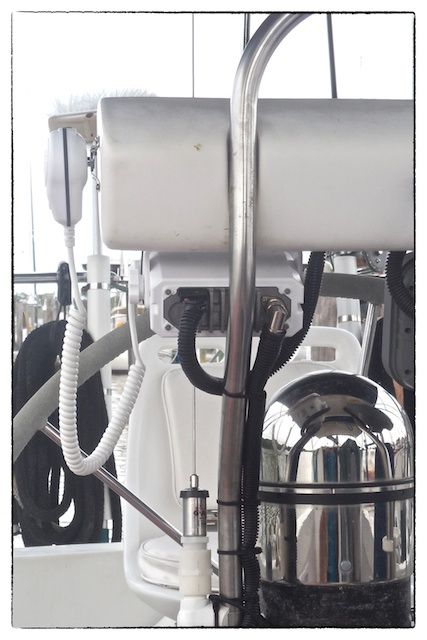 |
| To make a neatly finished installation, I covered all the cables with corrugated plastic cable covers and fastened them in place with black cable ties. |
 |
| Having up to 25 watts of power at the helm should eliminate any communications problems and treaty enhance our radio communication with the many bridge tenders and other snowbirds as we go down the Intracoastal Waterway. |
The total cost of this project was under $350 and installation took a couple hours but spanned a full week. (This project reminded me of the many hours I spent as a kid in Pennsylvania listening to my shortwave radio and collecting QSL cards from distant radio stations.)
 |
| A one-eyed Jack? |
This week we crossed off two more projects (one being the radio and antenna) from the "to do" list and added them to the "completed" list! We will be leaving in the beginning of October 2016 (25 months from now), whether all the projects are completed or not.
Addendum - August 23
After installing the radio and antenna, the radio would work fine for awhile then quit working--I couldn't even receive NOAA weather broadcasts. I noticed when I tapped on the base of the antenna mount it would work momentarily. After making a new antenna cable and having the problem repeated, I realized that the twisting of the antenna cable as I assembled the Railfast antenna mount may have caused the cable to short out.
So, I redesigned the mount such that there was a male coupling and an additional female coupling. I drilled a hole through the male coupling for the antenna cable to exit--this prevented the need to rotate any part of the mount (containing the cable) after the cable was installed.
 |
| Having the antenna cable come through one of the intermediate couplings (and not through the base of the Railfast mount) completely solved the problem of the cable twisting during assembly. |
Incidentally, even though the threads on the Railfast antenna mount are 1-inch diameter, the nylon fittings have pipe threads and 3/4-inch fittings are required in order to mate with the 1-inch threads on the antenna mount. The threads are not a perfect match but the nylon deforms sufficiently to make a solid structural connection.
Also of interest is while I'm trying to get rid of old un-tinned wire on our boat, the power cable on the new radio is un-tinned! @&$!?/&$
Addendum - September 12
After continuing problems receiving NOAA weather radio stations, I checked the antenna with an ohmmeter, checking resistance between the center conductor and the outer casing--it read 0 ohms (a short circuit). I called the antenna manufacturer and they said it shouldn't read a short circuit and the sent me a new antenna. When the new antenna arrived, I checked it the same way before attempting to install it--it, too, read a short circuit! The performance of the replacement antenna was somewhat better but it was very sensitive to location and when I touched the antenna the performance drastically improved.
Thinking that perhaps my multimeter was malfunctioning, I purchased a very small antenna (intended for racing boats) and measured the resistance between the center conductor and the outer casing--it measured about 500 mega ohms (which seems reasonable). However, the small antenna's performance was terrible--so, I immediately took it back to West Marine for a refund.
 |
| I already have an 8-foot long (Shakespeare-brand) VHF antenna mounted on the stern rail--I use it for the HF receiver. I decided to use this antenna for the helm-mounted VHF and get a more suitable (longer) antenna for the HF receiver. |
Using the 8-foot antenna on the stern solved all the reception problems with the helm-mounted VHF radio--I tested it with a temporary cable before installing the permanent cable. Now, I have to get a new antenna for the HF receiver.
 |
| Throughout this process, I found that Shakespeare makes a premium PL-259 connector (Style PL-259-8X-G)--it is constructed from gold-plated brass, has insulating washers to keep the braid from contacting the center conductor, and has a water-resistant rubber covering that fits over the outside of the coaxial cable at the connection. They are available at some West Marine stores. |
Fishing the new antenna cable through the port leg of the pedestal was a very time-consuming process because of the many instrument and power cables already running through this side of the pedestal. We ended up feeding a heavy copper wire (attached to the antenna cable) from the bottom and capturing it with needle-nosed pliers--it wasn't graceful but it worked.
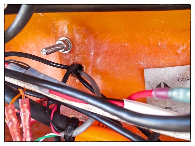 |
| Looking inside of the instrument pod with the instruments removed, we had to feed the new antenna cable through a hole (shown on left center of image) which already had four cables coming through it. |
The lesson that I have learned through this small project is that I have to do a better job of troubleshooting on future projects--it would have saved a lot of time and effort. The very first thing I should have done after realizing there was a problem was to use my multimeter to check cables and antennas.
Thanks for following our blog!
This comment has been removed by a blog administrator.
ReplyDeleteWoah! I'm really digging the template/theme of this website. It's simple, yet effective. A lot of times it's very difficult to get that "perfect balance" between usability and visual appeal. I must say you have done a fantastic job with this. Also, the blog loads extremely fast for me on Internet explorer. Outstanding Blog! kids blackout curtains
ReplyDeleteThis comment has been removed by a blog administrator.
ReplyDelete