Spaghetti Wires
Part 1: Identifying the Problem
--Blogpost written by Bob
As a mechanical engineer, I value order. In my career, my designs have always centered on simplicity and elegance with a sense of order. But, at the same time, some part of my work space (or part of my life) was in chaos. Usually, my desk was in chaos. At home, my workshop is usually in chaos. The chaos usually reaches a point where it becomes unmanageable and I have to stop everything I am doing and address it with a major (clean up and organizing) effort.
Well, chaos has appeared in one specific area on the boat, in the midst of an elegantly designed area. To set the stage, I'll describe the area (the electrical panels), what the area was like originally, the elegant design that followed, and the chaos that remains today.
The Original Electrical Panels
When I purchased my boat many years ago, there were a number of individual electrical switch panels (I think there were four identical panels holding seven switches in each panel) that were made from plastic and they were fastened to the bulkhead (just below the companionway) with wood screws--there was a big cutout in the bulkhead for all the switches contained in each panel. One or two of the plastic switch plates were cracked at the corners and the wood screws did not secure the panels very well in the already well-worn screw holes in the plywood. (The boat was 5 years old at this point.)
The Replacement Electrical Panels
One of the first boat projects I did after purchasing my boat was to completely redesign and rebuild this area. I made a plan for all the switching needs I could foresee in the future and made a drawing of the switches arranged in logical groups. When completely designed, I had four individual panels: one for AC switches, one for battery switching and monitoring, one for bilge controls and some extra space for future use, and a larger panel for all 12-volt onboard lighting and pumps. (The spacing between all the panels is perfectly uniform, I might add.)
All the panels are constructed from aluminum plate. The holes for all the switches were carefully spaced and drilled out on my drill press in my home workshop. All the screw holes were evenly countersunk for the flat head screws that are used to mount the switches. The panels were then painted with a zinc primer and spray painted with two coats of flat black (Rustoleum-brand, I think) paint. After mounting all the switches, I applied labels for each and every switch.
I made a new bulkhead from teak-veneered plywood to accommodate the new switch panels. The teak bulkhead is nicely varnished.
Three of the four panels are screwed in place like the original panels. However, unlike the original panels, I used brass inserts in the bulkhead to receive the flat head machine screws that secure the panels in place. The brass inserts are designed for frequent removal of the screws without the problem of worn out holes like the original design.
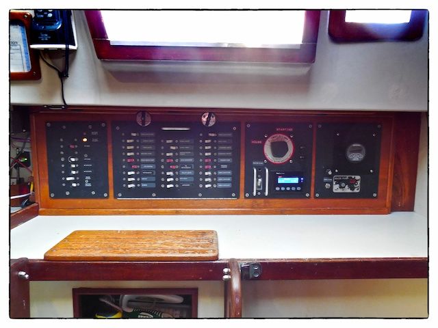 |
| The aluminum electrical panels are well designed and well made--they have held up well over the past 25 years. This view is looking aft from inside the boat. The navigation station is to the left and the quarter berth is to the right of the electrical panels. |
The fourth (and largest) panel (located second from the left in the above image) is actually mounted on a horizontal piano hinge so that, when opened, it reveals the wiring behind the panel. The wires from the switches to the terminal blocks are grouped together and contained in a flexible cover that protects them from chafe during the opening movement of the hinged panel.
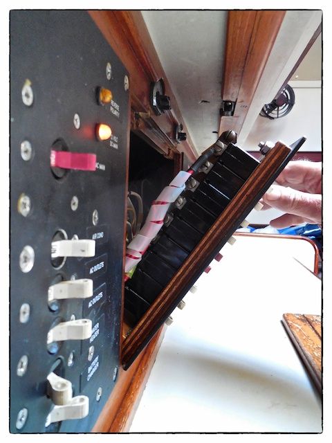 |
| The concept of having the main 12-volt panel hinged for access has saved a lot of time and aggravation over the years. |
Subsequent Rewiring
Over the years, I have replaced most of the un-tinned original wiring with new tinned wiring, upgraded lighting throughout the boat (I have overhead recessed lighting throughout the boat and additional lights where needed for reading), replaced and upgraded all pumps, and added a deck wash system. I added 12-volt refrigeration and central air conditioning over the years as well.
The Chaos
This weekend I had to add power connections for the WiFi Booster I was installing. When I opened the hinged door containing most of the 12-volt electrical switches, the chaos was obvious and it needs to be addressed soon.
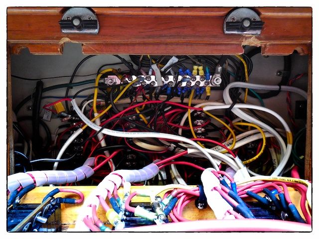 |
| Where do I even start? In this image you can't even see the three 8-terminal blocks behind the spaghetti wires! |
More on this subject later. Next up is our experience at the sailboat show...
Thanks for following our blog!
No comments:
Post a Comment