Auxiliary Diesel Tank
Part 3: Tank Installation
Auxiliary Diesel Tank
Part 3: Tank Installation
--Blogpost written by Bob
This blogpost picks up where Part 2 (Supports and Tank Ordering) of this subject (dated November 15, 2014) left off. The new 19-gallon aluminum fuel tank has been manufactured to my drawing by Florida Marine Tanks in Henderson, NC. My friend Bill and I drove to Henderson, NC (about 4-1/2 hours south southwest of Annapolis) to pick up the new tank.
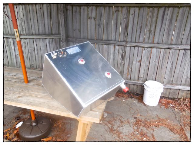 |
| Our new auxiliary fuel tank is shown sitting on a picnic table outside Florida Marine Tanks' shop in Henderson, NC. Florida Marine Tanks produces 100 tanks per day, supplying aluminum tanks to most boatbuilders in the U.S. |
This blogpost (Part 3) covers the installation of the new tank, the new deck fill connection, and the new fill, vent, and discharge hoses.
Raising Both Diesel Fill Connections
The diesel fill connection for the new auxiliary diesel tank uses the same location as the old discharge fitting for the holding tank. I purchased a used diesel deck fitting at Bacon's (for less than $15) to replace the old waste deck fitting.
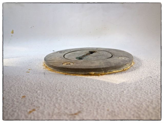 |
| The diesel fill connection for the primary fuel tank was mounted right on the deck and if the starboard deck drain was blocked. rainwater could accumulate above the level of the deck fitting and there would be a risk of getting rainwater in the fuel tank. |
Using Wally Bryant's idea, I decided to raise the diesel deck fittings 3/8-inch above the deck level to avoid getting rainwater into our diesel tanks in the event that the o-ring in the screw-on lid failed. So, I made two 3/8-inch thick plastic (white Starboard) donuts to fit between the fitting's flange and the deck.
 |
| I made the plastic donuts using hole saws for the inner and outer diameters and then rounded the upper (outer) edge with a router. |
The original deck fittings were fastened only to the outside skin of the deck with #8 flat head screws. When I installed the new deck fittings (with the plastic donuts) I used #10 cap screws which went completely through the balsa-cored deck, washers, and nylon-inserted nuts. (Of course, the balsa core was previously replaced with epoxy in the area around the deck connections--so, no worries about rainwater leaking into the balsa core.)
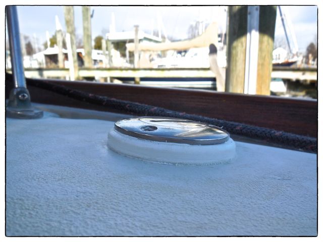 |
| With the newly raised deck fittings for both the primary and auxiliary fill connections, there is much less risk of rainwater entering the fuel system. |
Seating & Anchoring the Tank
When I made a trial fit up to make sure the tank would fit before starting the installation work, I noticed that on the outboard side of the tank there was about 1/2-inch space that needed to be filled (both vertically and athwartship on the outboard edge) so that the tank wouldn't wobble. I used plywood shims to make sure it was fully supported. Once the wooden shims were sanded down in spots and adjusted just right, I fastened the shims in place with epoxy and then coated them with epoxy for long-term durability.
Before permanently putting the tank in place, I attached stainless steel perforated strapping (purchased from Grainger) to the support structure at two opposing points on the mounting frames in two different directions, selecting the locations so that the strapping would not interfere with the tank connections. Each end of the strap was fastened with one 1/4-inch flat head screw and a nylon-inserted nut. The strapping has to hold the tank and its contents (about 160 pounds when full) from bouncing around in rough seas.
To create a soft bed for the new tank, I put two large beads of Sikaflex #291 adhesive/caulk on all surfaces where the tank contacted the support structure. Then, I sprayed the bottom of the tank with olive oil to prevent the tank from adhering to the adhesive/caulk and lightly pushed the tank down into position. I allowed the adhesive/sealant to cure overnight before proceeding further.
 |
| I used inexpensive 1/4-inch stainless steel turnbuckles (purchased at $11 each from Amazon) to pull the ends of the stainless steel strapping together. The turnbuckles are rated at 500 pound load. |
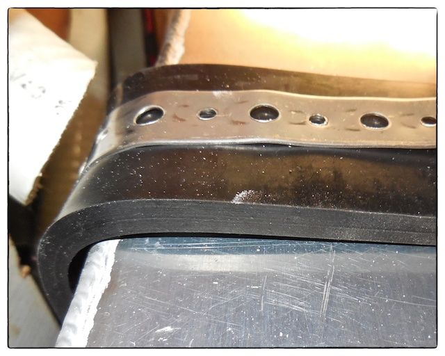 |
| I used 1/4-inch thick by 2-inch wide neoprene strips (purchased for $9 from Grainger) to isolate the stainless steel straps from the aluminum tank. |
I was very pleased about how well this tank restraint system worked out.
Fill, Vent, & Discharge Hoses
I designed the tank so that the top surface of the tank was 2 inches below the navigation station seat--this allowed just enough space to use low-profile brass elbows and hose barbs for all hose connections. (Since the brass fittings are so small compared to the large mass of the aluminum tank, I'm not concerned about galvanic corrosion.)
Fuel hoses must be constructed from nitrile--other types of rubber would quickly deteriorate when exposed to diesel fuel. The fill hose is 1-1/2-inch diameter while the vent hose is 1/2-inch diameter. The 10-foot long discharge hose matches the 3/8-inch diameter hose fittings on the selected diesel transfer pump. It is hard to believe that these three relatively short lengths of hoses cost $235!
I temporarily fit up the fill and vent hoses before permanently installing the tank--this was done so I could easily cut the hoses to length. I also fastened the discharge hose to the tank and ran it into the starboard cockpit locker. Once the tank was permanently installed, I clamped all the hoses to the hose barbs.
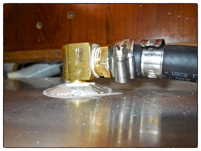 |
| I used low-profile brass elbows and hose barb fittings for all the hose connections. |
Wiring
I ran a 10-gauge ground cable between the ground connection on the new auxiliary fuel tank and the fill connection of the primary fuel tank--this connects both tanks together and the primary tank is grounded to the engine block. (There are a lot of different viewpoints on grounding diesel tanks--I've taken the most conservative viewpoint and grounded it.) I also ran a two conductor cable for the fuel gauge into the starboard cockpit locker for now.
Summary
The new tank is now rigidly attached to the support structure and all hoses and wires are connected to the tank. The tank area (under the navigation station seat) was finally closed up since it no longer needs to be accessed. The discharge hose and the wires run through the outboard aft bulkhead and into the starboard cockpit locker. The remaining work will be done in the starboard cockpit locker--one of my favorite places to work (just kidding).
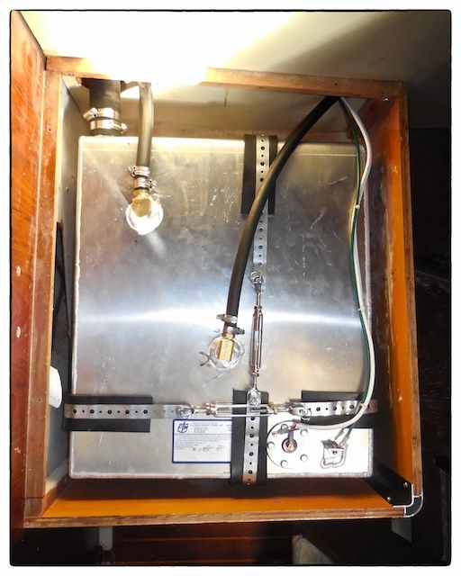 |
| The auxiliary tank is in place and completely connected at this point. |
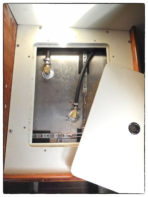 |
| The navigation seal frame is back in place and this shows the accessibility for the hose connections on the top of the tank. |
The cost of this phase of the installation was about $350 (not including the tank and delivery costs). We are up to about $850 for this project so far.
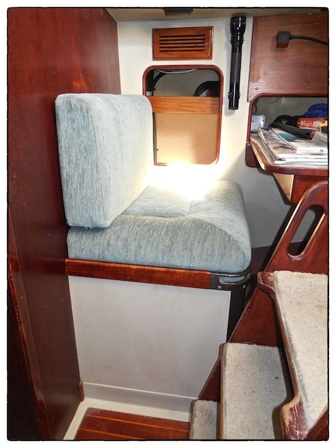 |
| The navigation station seat is all together and the cushions installed. |
The installation of the diesel transfer pump, the modifications to the existing fuel tank system, and connecting the fuel gauge to complete this project will be covered in the next blogpost on this subject (Part 4).
Thanks for following our blog!
Where did you put your holding tank if you were able to put a diesel tank under the nav seat (where the holding tank originally was)?
ReplyDeleteIn March, I will be installing a composting toilet which does not require a holding tank. It has been ordered but not delivered yet. This is one of the advantages of using a composting toilet--more available space for things like an auxiliary diesel tank.
ReplyDelete