Inverter Installation
Part 2: Mounting & Wiring
--Blogpost written by Bob
I keep hearing about boat owners installing 2000-watt inverters and using them to power a microwave oven, a small hair dryer, etc. It makes my selection of a 600-watt inverter seem a little wimpy but I'm confident that we don't really need more AC power. Even though we have a microwave oven at home and frequently use it, I don't want a microwave on our boat. I want to avoid the need for gasoline-powered onboard generators, more and bigger batteries, and more than our 300 watts of solar panels. I'm trying to strike a balance between conveniences and lifestyle simplification.
The intended inverter location is very close to our starboard battery bank--so, I decided to wire it directly to this (#1) battery bank to minimize the length of wiring and to keep it simple. Our inverter will be used intermittently--not on a daily basis--so, I don't see the need to wire it so that either battery bank can feed it.
Mounting
Mounting the inverter on its side with the bottom bolted to the outboard panel under the navigation station desk seemed to be preferable. Allowing 2-1/2 inches behind the inverter for ventilation, the inverter protrudes out beyond the face of our technical manuals by about 2-1/2 inches.
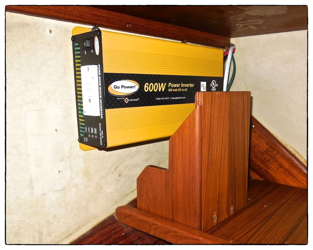 |
| I mounted the inverter using four 1/4-inch hex head lag screws that I was able to install with a socket wrench with a six-inch extension. I cutout a small portion of the fixed bookend so that there would be a 1-inch clearance all around the inverter for ventilation. |
Size of Power Cables
The 600-watt inverter draws 50 amps @ 10.5 volts (minimum) DC at the surge power rating. The roundtrip distance for the wiring is approximately 12 feet. For a 3% voltage drop, the cable size should be 6 AWG. 6 AWG is two sizes larger than my current wire crimping tool can handle--so, I had to crimp the terminals to the cables at Fawcetts.
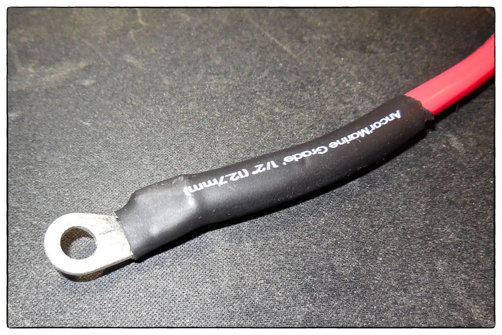 |
| All the cables have crimped end connections. The heavy duty crimper makes a deep indentation in the terminal when it is clamped to the cable. I installed heat shrink tubing to further protect the crimped ends. |
I wired the remote on/off to a circuit breaker using 16 AWG cable since this line does not carry the amperage feeding the inverter. There is no power supplied to this cable--it is simply a make or break connection.
Fuse and Fuse Holder
I purchased a 50-amp fuse and fuse holder (made by Blue Sea Systems) at Fawcetts to wire into the system. This is protection against an overloaded inverter or the accidental shorting of the feed cables.
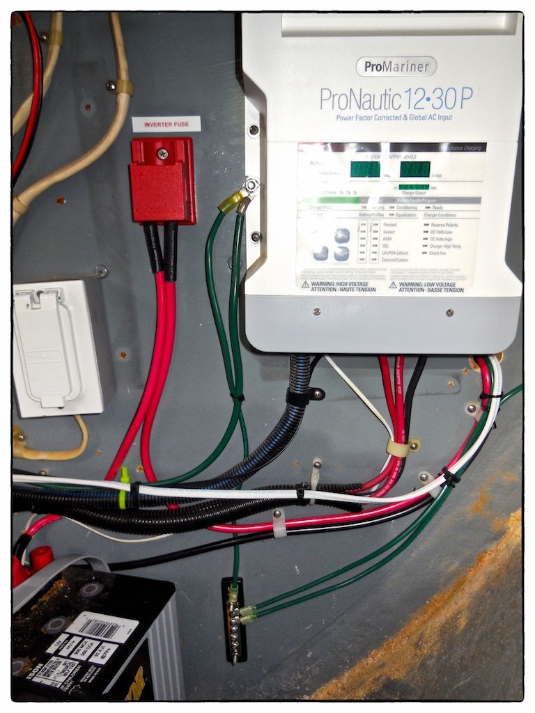 |
| The installation of the Blue Seas' fuse holder (upper left portion of the image) eliminated the need for an additional terminal block. Since the inverter had to be grounded along with the auxiliary fuel tank, I added a substantial bus bar (lower center of image) for this purpose |
Summary
Since our last blogpost, I was able to purchase a 12-volt charger for batteries for one our three cameras (they all have different batteries!)--this further reduces the need for the inverter for additional small loads.
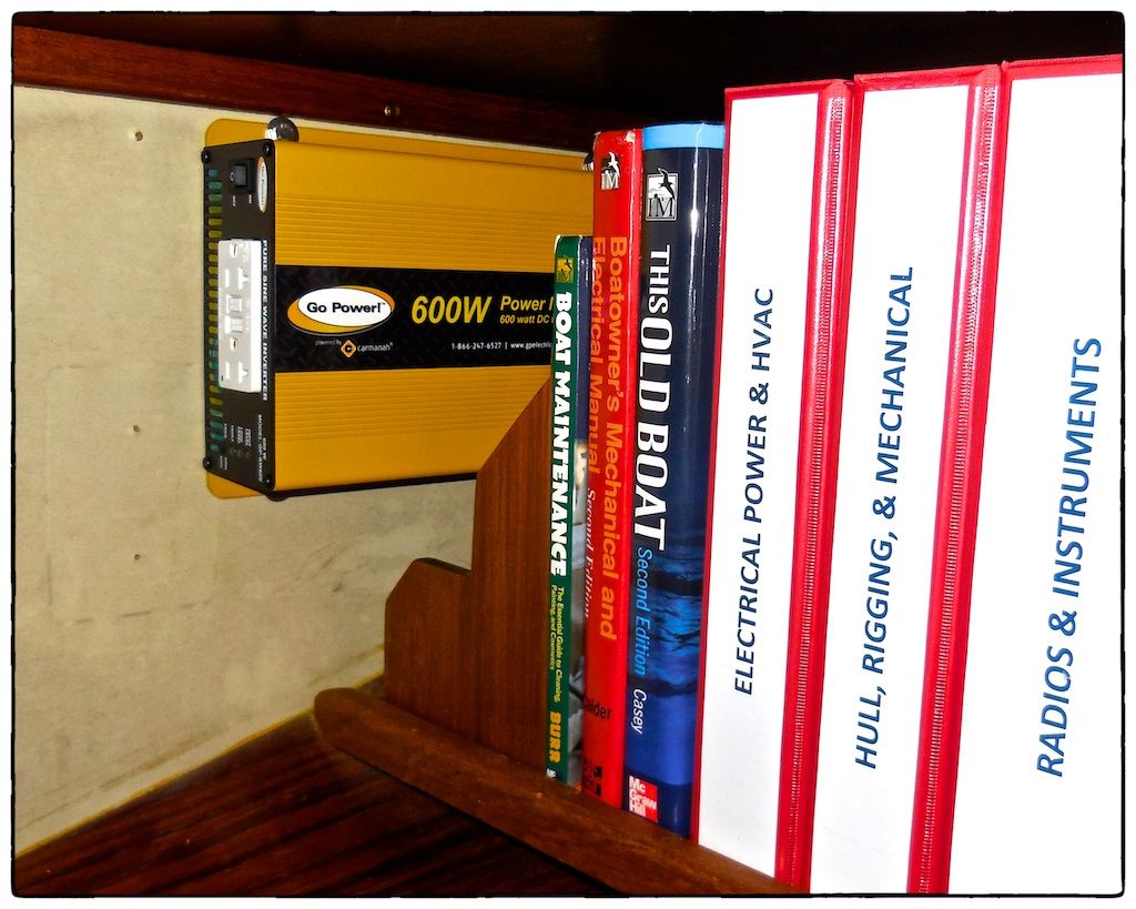 |
| The inverter has been mounted below the navigation station desk. The entire cost of this project was less than $425. |
Many times I feel grateful that we are refitting OUR old boat and not buying another boat that someone has equipped to their liking. This inverter installation is a good example of a refit item that is tailored to our needs--not someone else's needs.
Thanks for following our blog!
No comments:
Post a Comment