Hooking up AIS Receiver - Part 1
--Blogpost written by Bob
The Automatic Identification System (AIS) is an automatic tracking system used on ships and by vessel traffic services (VTS) for identifying and locating vessels by electronically exchanging data with other nearby ships, AIS base stations, and satellites. With AIS connected, ships transmitting AIS information will show up on our chart plotter--this information is extremely valuable, particularly while crossing the gulf stream during the night and navigating passages in the Tongue of the Ocean between islands in the Bahamas.
During my first gulf stream crossing in late 1991, we didn't even have GPS or a chart plotter, let alone AIS. I used LORAN for navigation at that time and in some areas of the Bahamas, the position error was on the order of 1000 feet or more. Compare this to the position error of much less than 100 feet with today's GPS units. All of these advancements during the last 25 years have made sailing passages much easier to navigate and safer.
 |
It wasn't as simple as hooking up power and a data cable because of the differing electronic protocols involved with our onboard equipment. |
The AIS receiver is located in the navigation station below deck while the ACTISENSE converter and most of the wiring is located in the navigation pod on the steering pedestal in the cockpit.
About AIS
AIS uses electronic messages to transmit ship information, speed, heading, and destination. The electronic messages are sent and received on two channels (AIS-1 and AIS-2) to avoid interference problems, and to allow channels to be shifted without communications loss from other ships.
Channel access is performed independently on each of the two parallel channels. For periodic repeated messages, including the initial link access, the transmissions alternate between AIS-1 and AIS-2. This alternating behavior is on a transmission by transmission basis, without respect to time frames. Transmissions following slot allocation announcements, responses to interrogations, responses to requests, and acknowledgments are transmitted on the same channel as the initial message.
Since each ship transmits on two alternating channels, a dual channel receiver results in more frequent updates than a single channel receiver.
Connection Diagram
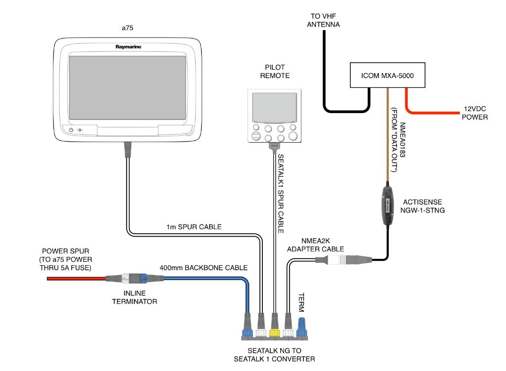 |
With the help Fred Street and his basic wiring diagram and equipment setup, the installation was pretty straight forward. |
The connection between the AIS receiver and the ANTISENSE converter in the navigation pod used a relatively small diameter 3-conductor instrument cable. This cable runs up through the pedestal and into the instrument pod.
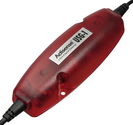
ACTISENSE Converter
The ACTISENSE NGW-1 NMEA 2000 Gateway is the easiest way to link between a boat's old and new data networks.
 |
The ANTISENSE NGW-1 converter converts NMEA 0183 data from the AIS receiver into NMEA 2000 data (and SeaTalk NG) for the chart plotter. |
Some of the functions that can be handled by the converter include the following: upgrade NMEA 0183 equipment to NMEA 2000, allow NMEA 0183 devices to receive vital NMEA 2000 data, use the NMEA 2000 bus to multiplex several NMEA 0183 signals together, and configure a NMEA Reader. Fred Street configured the converter before he shipped it to me. In our case, our chart plotter and other instruments use RayMarine's SeaTalk NG while the new AIS receiver uses NMEA 0183.
I mounted the ACTISENSE converter inside the navigation pod using 3M Dual Lock Re-closable fastener tape, each side of which was adhered by VHB tape.
I mounted the ACTISENSE converter inside the navigation pod using 3M Dual Lock Re-closable fastener tape, each side of which was adhered by VHB tape.
AIS Receiver
I purchased the ICOM MXA-5000 AIS dual-channel AIS receiver for the sole purpose of receiving AIS data from ships. This receiver costs about $250. Incidentally, some newer VHF transceivers have built in AIS capability but I didn't want to change out one of my two VHF transceivers.
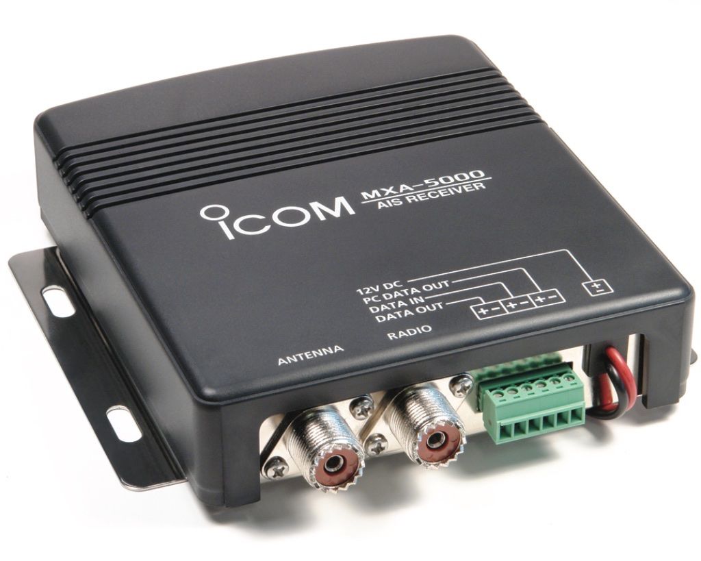 |
| The ICOM MXA-5000 is a dual channel AIS receiver. |
I really like the quality and reliability of ICOM communications equipment. We have two ICOM VHF transceivers--one in the navigation station and one at the helm. We also have an ICOM handheld VHF transceiver on board. It was natural to stick with ICOM for the AIS receiver.
While the AIS receiver could be mounted almost anywhere, by locating it in the navigation station, it would be sharing the masthead antenna which would get better signals than the secondary VHF antenna mounted on the stern rail.
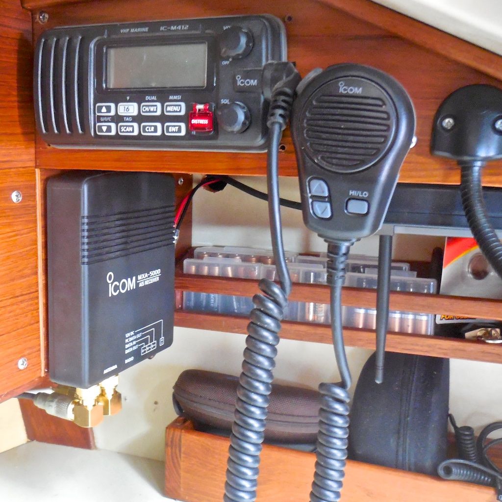 |
| I removed a fan that was located in navigation station. The AIS receiver tucked in nicely below my primary VHF radio--this made very short runs for the antenna cable. |
I used Shakespeare-brand PL-259 L-shaped coaxial connectors and I mounted the receiver using 3M Dual Lock Re-closable fastener tape--this way it is easier to remove and reinstall than using bolts or screws.
Feeding Data Cable Through Pedestal
Feeding the instrument cable through the steering pedestal was the most time-consuming part of this project--it took 6 hours! Part of this time was spent trying to figure out what was going on with some existing wiring. There was a black cable that came out to the hole from the pedestal into the instrument pod that was cut off and not connected to anything.
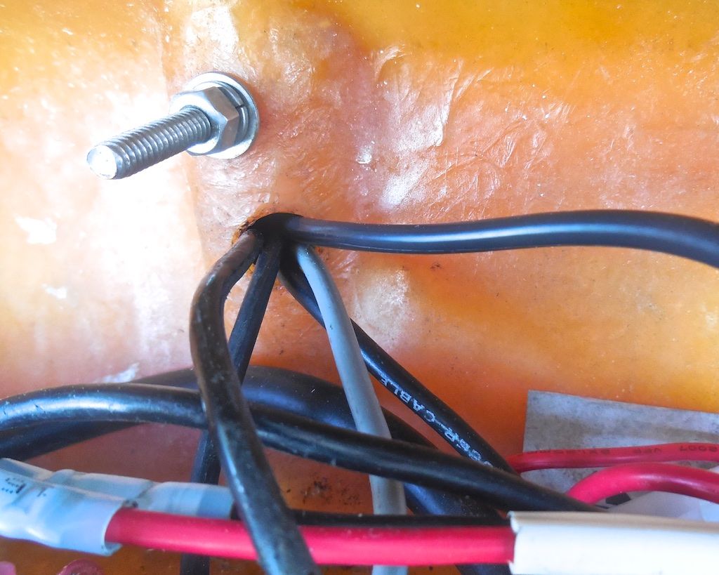 |
| This photo shows the old cables coming from the pedestal into the navigation pod. There are four black cables and one gray cable--one of the four black cables didn't connect to anything. |
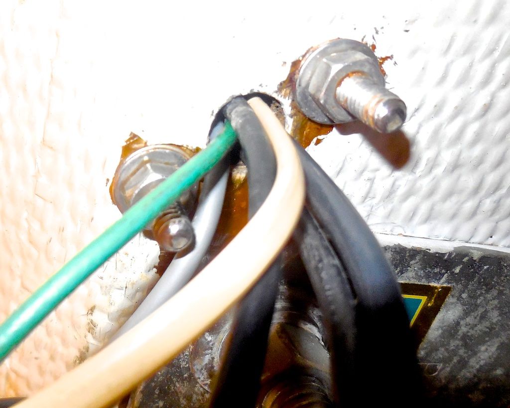 |
| This photo shows the old cables going into the steering pedestal from below deck. There are three black cables and one gray cable and one green cable--this doesn't match what is coming into the navigation pod above. |
Under the deck where the cables came from the pedestal, there was a white wire and a green wire that didn't exit at the top. We snipped the white wire and the green wire from below and pulled the black cable out from the top. As it turned out, the white wire and green wire were spliced to the unused black wire within the pedestal. (We may have saved a lot of time using the old cables as messengers to pull up the new cable.)
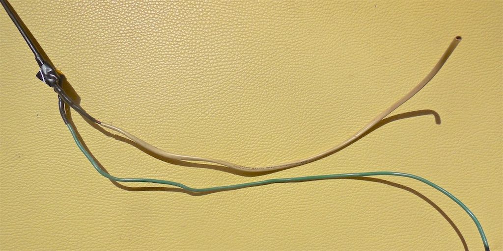 |
| This wiring was apparently part of a previous instrument connection that was replaced after a lightning strike several years ago. |
After we removed the old unused cables, we fed the new cable into the pedestal from the bottom, pushing the wire up into the pedestal. Maggie was at the instrument pod awaiting its arrival and snagged it with a bent coat hanger wire.
Wiring New Components
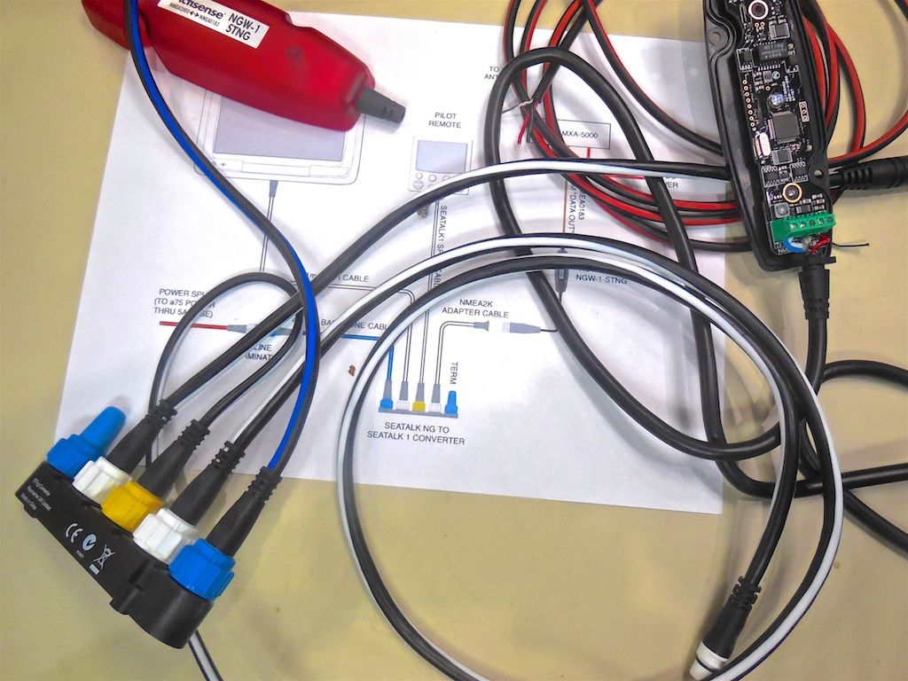 |
| While it was overcast and cool in the morning, I connected all the cables (except power and data) on a table so that I knew I had all the components and understood how they are to be wired together. All of the above wiring will be inside the navigation pod when completed |
Fastening Components
All equipment (including the receiver, the ANTISENSE converter, a power terminal, and a instrument cable terminal) were fastened using 3M Dual Lock Re-closable Fastener. This is a very heavy duty plastic fastener tape with VHB backing tape. I have had a 2-inch wide x 10-foot long roll for a long time but it is available from Amazon. I cut 3/4-inch by 2-inch wide pieces for fastening all equipment. This proved to be a good replacement for screws or bolts through the navigation pod.
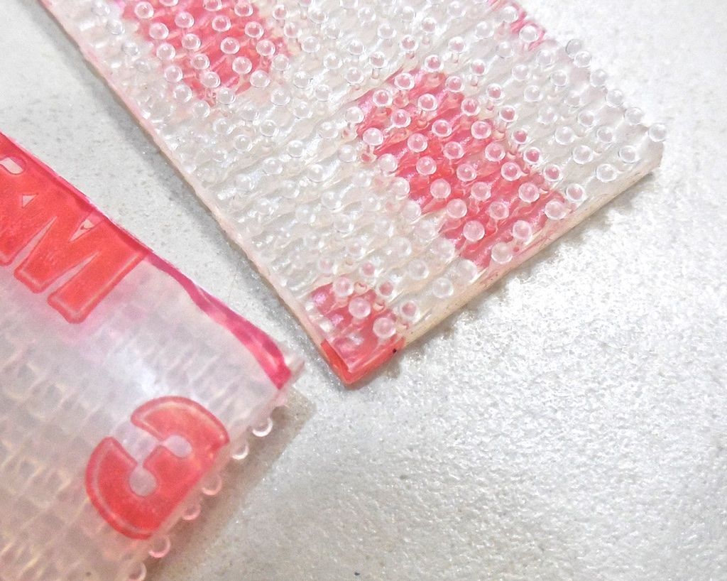 |
| This is a close up view of the fastener tape we used for all equipment on this project. |
Summary
This project is not complete yet. The AIS did not function with my chart plotter, probably because the chart plotter's software needs to be updated--it hasn't been updated since 2009 when it was installed and there have been several software updates issued by RayMarine dealing with AIS since then. Oh, and did I mention you can't use a CF card rated at over 2 GB--all mine are 8 GB (for my Nikon camera). So, must wait for smaller CF card to arrive...
 |
| My navigation pod is open and awaiting more troubleshooting. This is how the project stands right now. |
This project's cost was about $500 total and it took me about 16 hours so far, most of which was dealing with the old wiring mess in the pedestal. I can't count this project as complete yet--more in Part 2.
Thanks for following our blog!
No comments:
Post a Comment