Auxiliary Diesel Tank
Part 2: Supports & Tank Ordering
--Blogpost written by Bob
Most sailboats, including ours, don't have enough fuel capacity for cruising. Most cruisers supplement their tankage by carrying jerry jugs of diesel fuel. Our (Part 1) blogpost of April 22, 2014 described our new auxiliary fuel tank system, which will prevent the need to carry jerry jugs of diesel fuel. (Our four jerry jugs stored on deck will be used for drinking water and gasoline for the dinghy.)
This blogpost (Part 2) covers the installation of tank supports and building a cardboard model of the new auxiliary diesel tank. Part 3 (about 2 months from now) will cover the actual installation of the new (custom-manufactured) aluminum tank and Part 4 will cover the installation of the diesel transfer pump and connection into the existing fuel system.
Cavity for the Tank
 |
| The location of the new auxiliary diesel tank is under the seat in the navigation station where the holding tank was originally located--our upcoming conversion to a composting toilet has allowed us to remove the old holding tank and create the space for an auxiliary diesel tank. (Expanded foam was the only thing that supported and held the plastic holding tank in place.) |
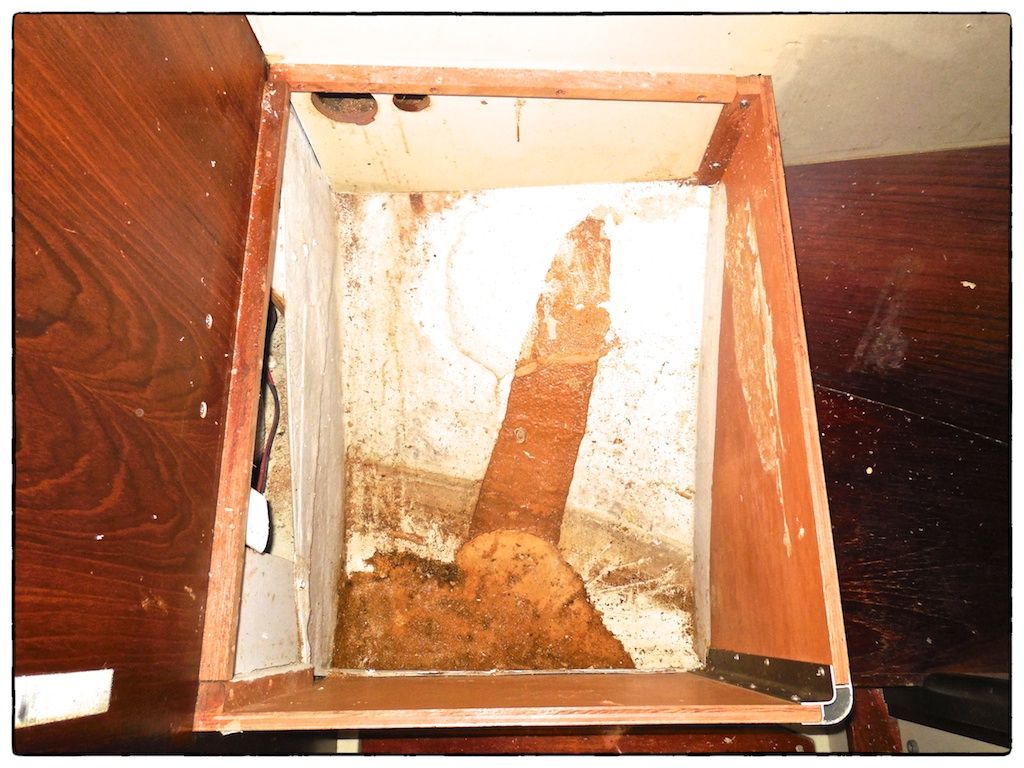 |
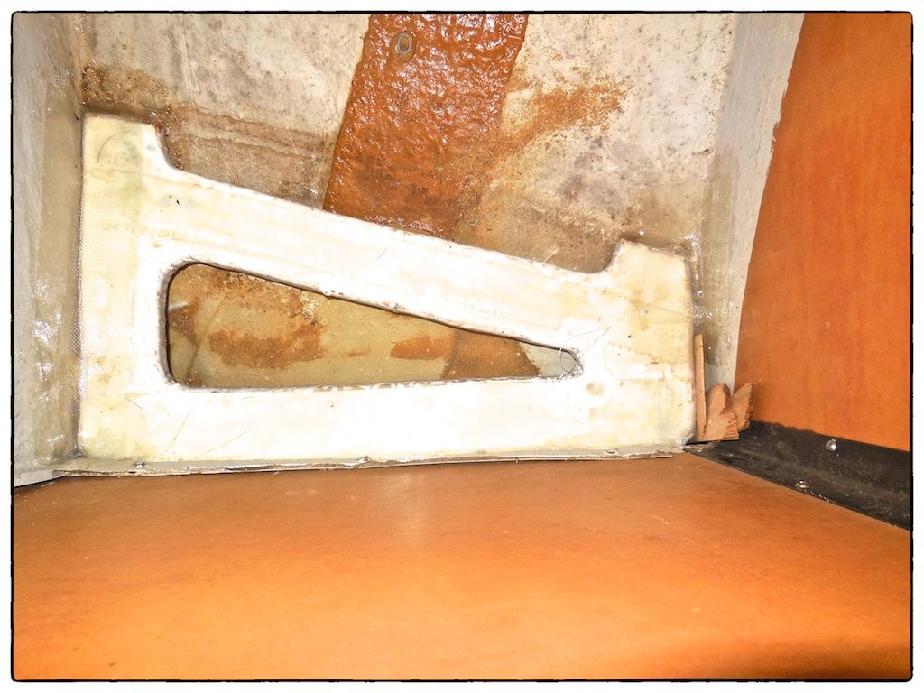
| Once the holding tank was removed, I removed all the expanded foam that supported the old plastic holding tank--it turned out to be a little deeper cavity than I expected. |
It was clear that at one time, there was some liquid (it had long since evaporated) that resided in the bottom of this cavity and there was no drain hole. So, my first order of business was to make a suitably-sized drain hole into the next cavity as close to the bottom as I could make it, using a 1-1/2-inch diameter hole saw--by using a relatively large hole saw I could make the bottom of the drain hole very close to the bottom of the cavity.
Flat Base for the Bottom of the Tank
The next step was to construct a flat base that forms a level support for the lowest area of the new tank and still allows for drainage of any liquid that ends up under the tank. After making a cardboard template, I constructed the base from 3/4-inch plywood and completely covered it with layers of fiberglass to make it waterproof and strong. There was an elongated hole in the center to promote drainage and keep weight to a minimum. (This elongated hole was also very helpful when I later bolted the angle frame to the base--it allowed access under the base plate.)
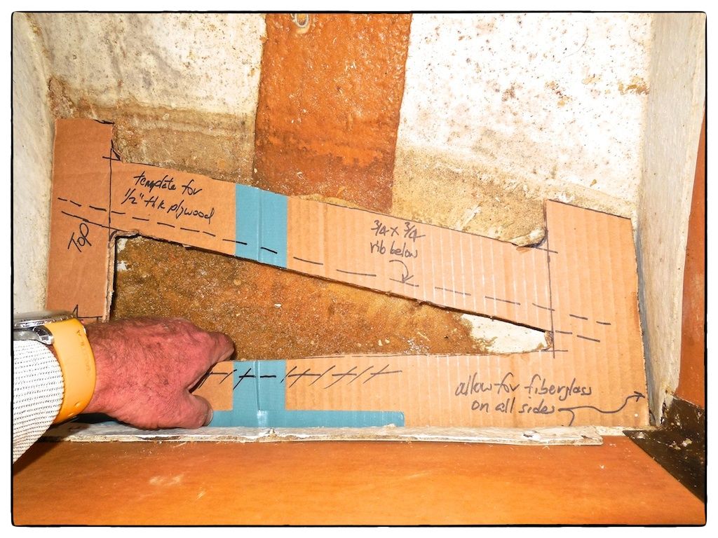 |
| The cardboard template for the tank's base support is shown being held in place. |
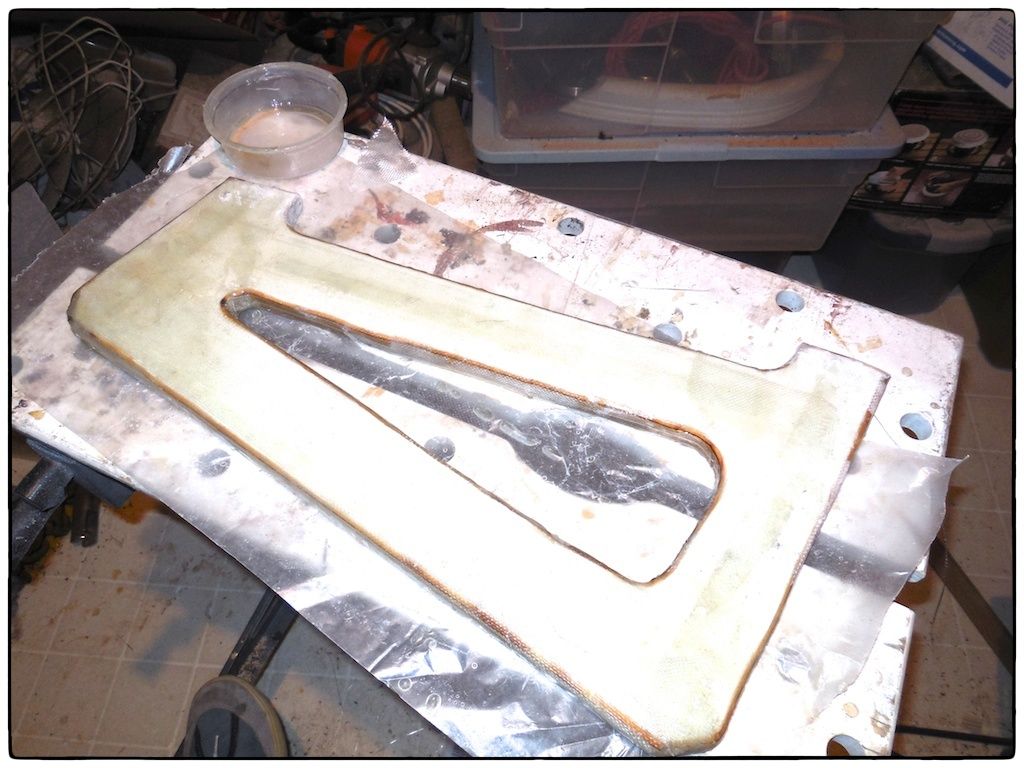 |
| The tank's base support was constructed in my home workshop. |
 |
| The new tank base was temporarily wedged in place while temporary fiberglass tabs cured overnight. |
Prior to installation of the new base, I roughed up the painted fiberglass and removed all remnants of foam (using a wire brush wheel on a portable drill) in the cavity where the base was being tabbed into the existing fiberglass. The new base was temporary wedged into place and leveled--I used small fiberglass tabs at three spots. Once the three spots cured (overnight), I removed the wooden wedges and fully tabbed the base in place.
Angle Frame Around the Tank's Perimeter
I ordered 2 x 2 x 1/4 FRP angle from Grainger to make a lip around the base of the tank. Since the FRP angle defined the perimeter of the bottom and sides of the tank, I had to work up the design of the tank as I went along. The fact that the cavity was not perfectly rectangular made this operation more challenging--I wanted the plan view of the tank to be rectangular and with 90-degree corners because it is easier to define and convey to the tank manufacturer. I started the layout of the angle on the two sides that were perpendicular to each other and then continued around the perimeter. Both sides of the angle were tabbed in place continuously with at least two layers of 4-inch wide fiberglass tape. I also used five through bolts between the angle frame and the base plate where straps would be fastened to hold the tank in place.
 |
| The angle frame spans the base support and the contour of the tank cavity. The angle frame in the plan view is perfectly rectangular while the cavity is not perfectly rectangular. (The wide angle lens used for this image creates a distorted view.) |
Measurements & Cardboard Model
 |
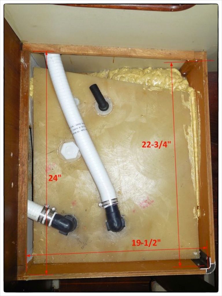
| The next step was to document all the dimensions from the underside of the seat--this involved making vertical measurements at all six points. Similarly, horizontal measurements were taken with respect to the two perpendicular sides of the cavity. |
I made a scale drawing of all the measurements and the angle frame itself. Knowing that a frame protruded under the level of the seat base by 7/8 inches and that I had to fit in a 1/2-inch elbow for the tank vent (not under the frame), I could define the upper surface of the tank as being about 2 inches below the lower surface of the seat. With all this information I was able to determine the exact outline of the new tank--a scale drawing of the tank was made at this point.
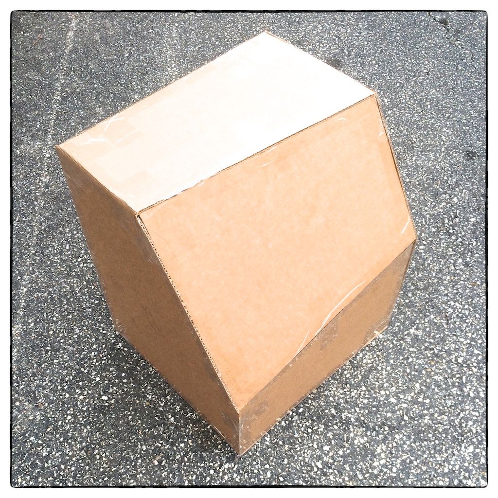 |
| To test the accuracy of the drawing and to properly locate all tank connections, I made a cardboard model of the tank. It is shown here lying on the inboard side and exposing the angled bottom. |
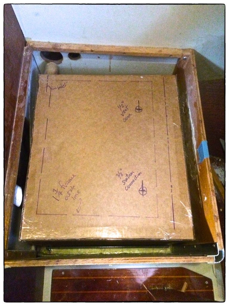 |
| As shown, the cardboard model fits into the supports perfectly with at least 1/8-inch clearance all around--this was after an on-site adjustment to the model. I marked the cardboard model with the locations of all 3 fittings (1-1/2-inch inlet, 3/8-inch outlet, and 1/2-inch vent) and added them to the drawing. |
Summary
Using all the final dimensions of the tank, I calculated the volume--it turned out to be 19 gallons. (It would take 4 jerry jugs to carry this much diesel fuel on deck.) The 19 additional gallons will stretch our refueling interval by 27 hours of runtime or over three 8-hour days.
The addition of the auxiliary fuel tank brings our total fuel capacity to 51 gallons (but approximately 3 gallons total are below the outlet suctions and are unusable). At cruising speed, the total tank capacity will provide about 72 hours of runtime or nine 8-hour days. The new tank was ordered and it will be delivered in 5 to 6 weeks.
Thanks for following our blog!
No comments:
Post a Comment