Spaghetti Wires
Part 2: Fixing the Mess
--Blogpost written by Bob
The wire mess behind the hinged electrical panel is what I call the spaghetti wires (refer to my blogpost of October 14, 2014). I've put off the project of organizing them for a long time now. Knowing that I soon had to add wiring for the diesel transfer pump and the inverter, I decided I can't put this project off any longer.
After giving this little project a lot of thought, I decided to tackle one terminal strip (of the three) at a time. By disconnecting one wire at a time, I could identify and label each one. I decided to make a suitably sized hole near the bottom of each terminal strip and bring each terminal strip's wires through the corresponding hole in the bottom of the electrical cabinet. By making the hole after the wires were labeled and disconnected, rerouting the wires upon reconnection would be much easier.
Disconnecting and Labeling the Wires
Well, it didn't work out exactly as planned since the most recently installed wires were blocking wires on the port terminal strip, our selected starting point. A lot more wires had to be removed than just those on one terminal strip.
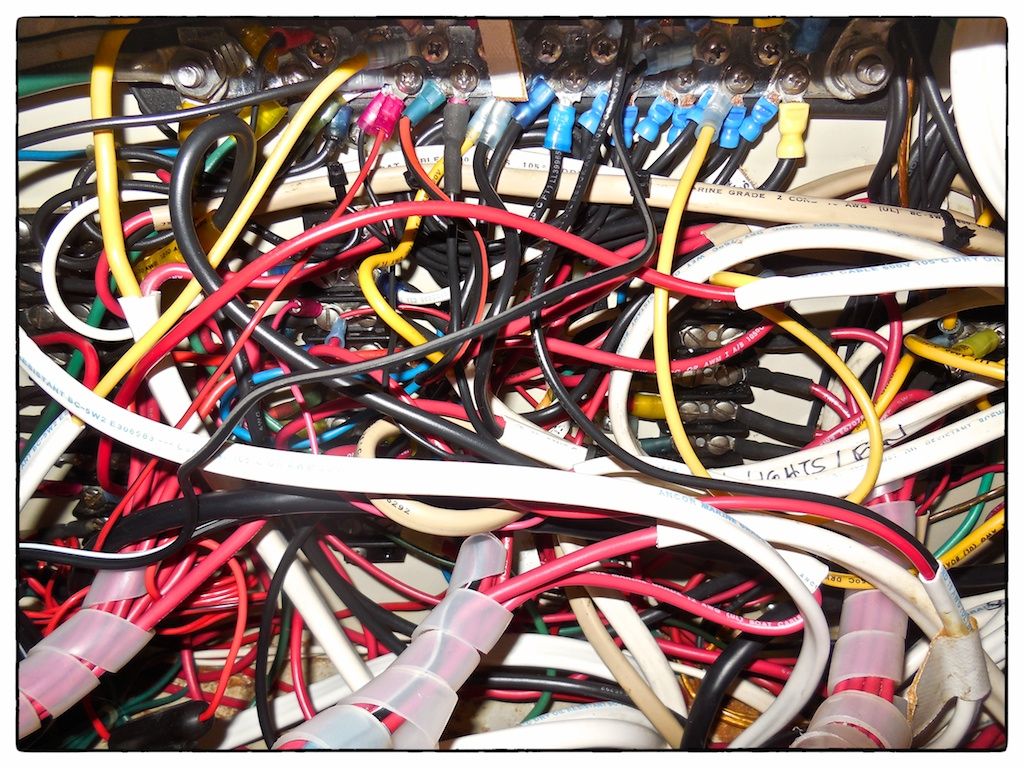 |
| This is what the spaghetti wires looked like when we started. |
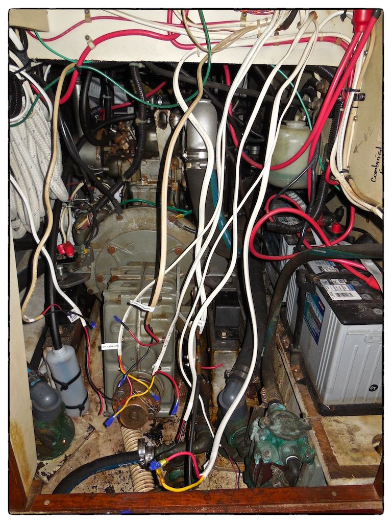 |
| As we disconnected each wire they were left dangling into the engine room below the electrical cabinet. Note all the white labels on the wires. |
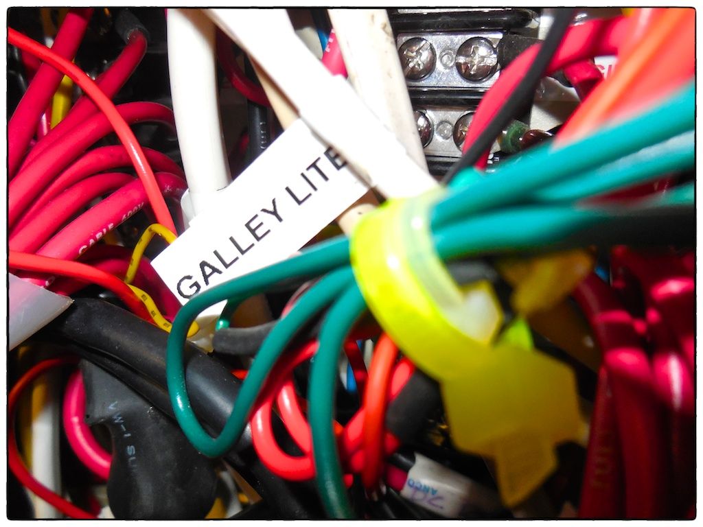 |
| I made individual labels using my Dymo label maker and attached them to each cable when removed. |
Improving Power Feeds
I decided to add a copper bar on the positive feed side of the circuit breakers on the middle column of circuit breakers like used on the port and starboard columns of breakers--the center column used jumper cables which added to the complexity of the wiring. I ordered a 1/8-inch x 3/4-inch x 12-inch long copper bar from OnLine Metals and drilled holes to match the spacing of the screws on the circuit breakers. I relocated the copper bar on the port circuit breakers to the center circuit breakers (8 circuit breakers in a column) and made the new bar to fit the port column of circuit breakers (9 circuit breakers in a column).
 |
| Drilling the copper bar was a lot more difficult than I imagined since copper is relatively soft. Even using a lubricant, the holes in the copper bar were made very slowly and the copper bar got quite warm. |
The power feeds to the electrical panel and between banks of circuit breakers were still old un-tinned cable--I replaced these with new cables custom made using tinned (2 AWG) cable.
Replacing the Terminal Strips
The existing three terminal strips on the bulkhead had 8 terminals each, for a total of 24 circuits. The port and starboard column of circuit breakers had 9 circuits while the center column had 8 circuits, for a total of 26 circuits. I replaced the old terminal strips with 3 new ones having 10 circuits each, for a total capacity of 30 circuits. This allowed me to get rid of a small extra terminal strip that made the wiring extra confusing. (The old and new terminal strips were rated at 30 amps.)
I drilled two additional 1-1/2-inch diameter holes in the bottom of the electrical cabinet at the base of two terminal strips so that the rewiring could be simplified even further by feeding the wires to each terminal strip from immediately below.
I added an additional bus bar on the port side to accommodate twenty additional negative or ground wires. (There are still a lot of old ground wires that are connected to the bus bar. I don't know how to tell what purpose they each serve--so, I left them in place for now.
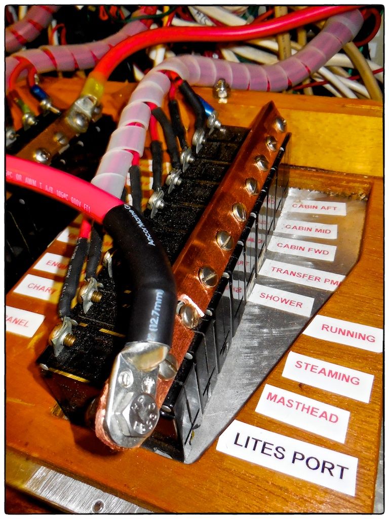
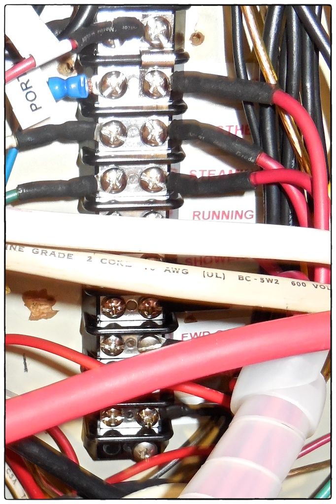 |
| I applied a label next to each positive terminal with the name of the cable's function, matching the label on the electrical panel. |
Reconnecting the Wires
This was relatively easy for all but two unlabeled cables. It took about 3 hours to reconnect everything except the two unlabeled cables--these two cables took about 20 minutes each to figure out what they were for. However, the reconnected wires, even though labeled, still look like a mess.
One little problem I encountered involved the varying screw size on the back of the circuit breakers--some are 8-32 and others are 10-32. Since new ones are all 10-32, this is probably something that changed over the past 30 years since my boat was built.
Relabeling Some Circuit Breakers
As part of this project I had to relocate some circuits, allow for the future addition of the inverter and diesel transfer pump, and do some relabeling on the panel. I was able to find new labels for a couple of the relocated circuits at Fawcetts. Fawcetts pointed out to me that Blue Sea Systems will custom make a label (for $5) if I can't find one. Sure enough, there were two labels I couldn't find at Fawcetts:
DIESEL TRANSFER PUMP
WIFI BOOSTER
I ordered these two custom made labels from Blue Sea Systems.
Changing the Panel Lights
I noticed that one of the panel lights above the electrical panels had recently burned out. These are small 1-watt utility lights with very small permanently installed bulbs--they were made by Perko. The only place I could find a replacement was Discount Marine Supplies. I think Perko discontinued making them sometime after I installed them maybe 20 years ago.
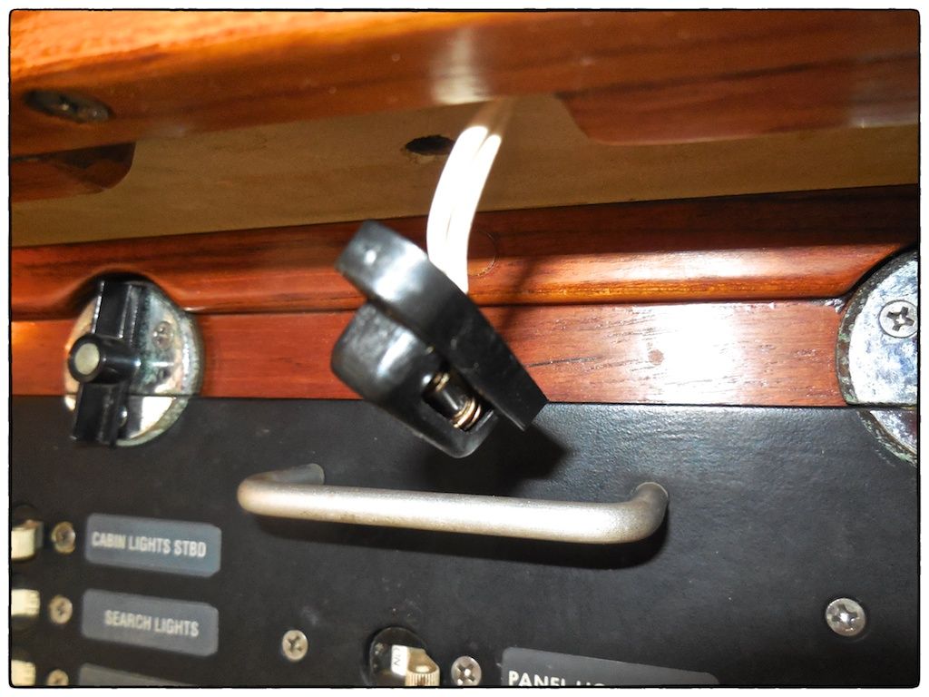 |
| This is the old black utility light partially removed from above the hinged electrical panel--the now ones are white. |
Rather than making one of the three lights white and having the older two as black, I ordered enough new lights to change all of them to white lights.
Summary
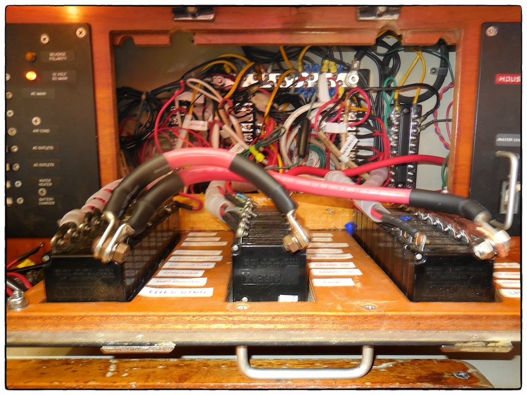 |
| While the wiring behind the hinged panel is not as neatly organized as I would like, it's better than it was and all terminal strips, wires, and circuit breakers are now properly labeled. |
As soon as we get a weekend day without some type of winter precipitation, Maggie and I intend to check that every single circuit breaker will work as intended by turning on each circuit breaker (alone) and making sure that it turned on the intended equipment. I am also going to try and bundle some of the wires better.
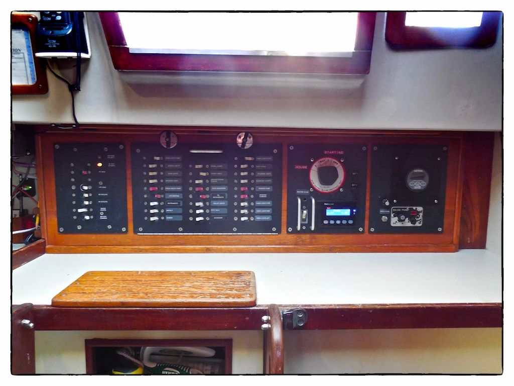 |
| The complete electrical panel located just below the companionway on s/v Rainy Days. |
This project cost very little in materials (less than $100) but took a lot of time and perseverance. I am so glad this project is nearly done so I can soon complete the installation of the auxiliary diesel tank and install our new inverter.
Thanks for following our blog!
Hiya Robert,
ReplyDeleteWhat an absolutely crazy difference in how it looks from when you started to now.
It is not just one mess of cables it actually looks welcoming and neat, specially a good job on the labels to help get everything organized the way it should be.
Really looking forward to seeing your other projects and I hope the Dymo will be included in more of those adventures!
With best regards,
Jesper K
DYMOSupport