Engine Gauge Re-wiring: Part 1
Engine Gauge Re-wiring: Part 1
--Blogpost written by Bob
After completely cleaning up the spaghetti wires, I proceeded into the area aft of the quarter berth to address the complete mess I call the engine gauge wiring. All of the wiring in this area is the old un-tinned wire connected to harnesses that was typical of the original boat wiring.
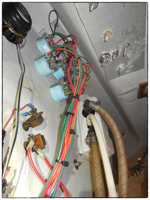
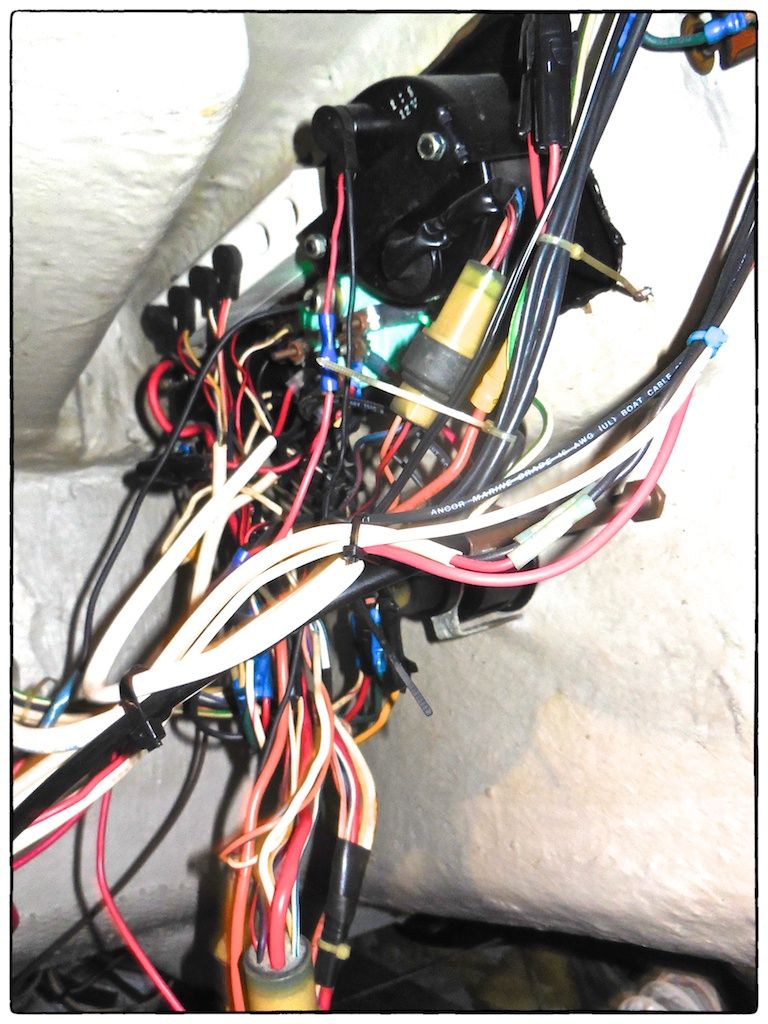 |
| This mass of wires with the old wiring harnesses has resided just behind the engine control panel for over 30 years. |
My experience with the old un-tinned wire is that it can fail at any time (aggravated by moisture at the junctions) and it usually creates an intermittent problem first that is almost impossible to find. I experienced the deceptive failure of un-tinned wires on the automatic bilge pump and I've already experienced problems with the tachometer and the engine hour meter. So, I had to decide whether to address a wiring problem later while cruising or tackle the big mess now, spending a nice spring weekend or two replacing all the wiring. I don't know anyone who tackled the engine wiring as part of their boat rewiring. I guess I'll find out why...
Adding Terminals for Gauges
In my home workshop I made a teak panel to mount an 8-terminal strip for connecting the gauges to sending units, a 4-terminal strip for connecting the gauges to power, and a bus bar. Before installation I affixed labels made with my Dymo label maker (I love this thing!) and then coated them with epoxy for maximum durability since the panel is close to the engine room.
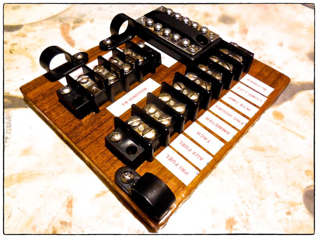 |
| After the epoxy coating cured I fastened both terminal strips and the bar bar to the teak panel in their designed position. I also fastened plastic cable loops to pass the wires through so that it would remain neat and organized. |
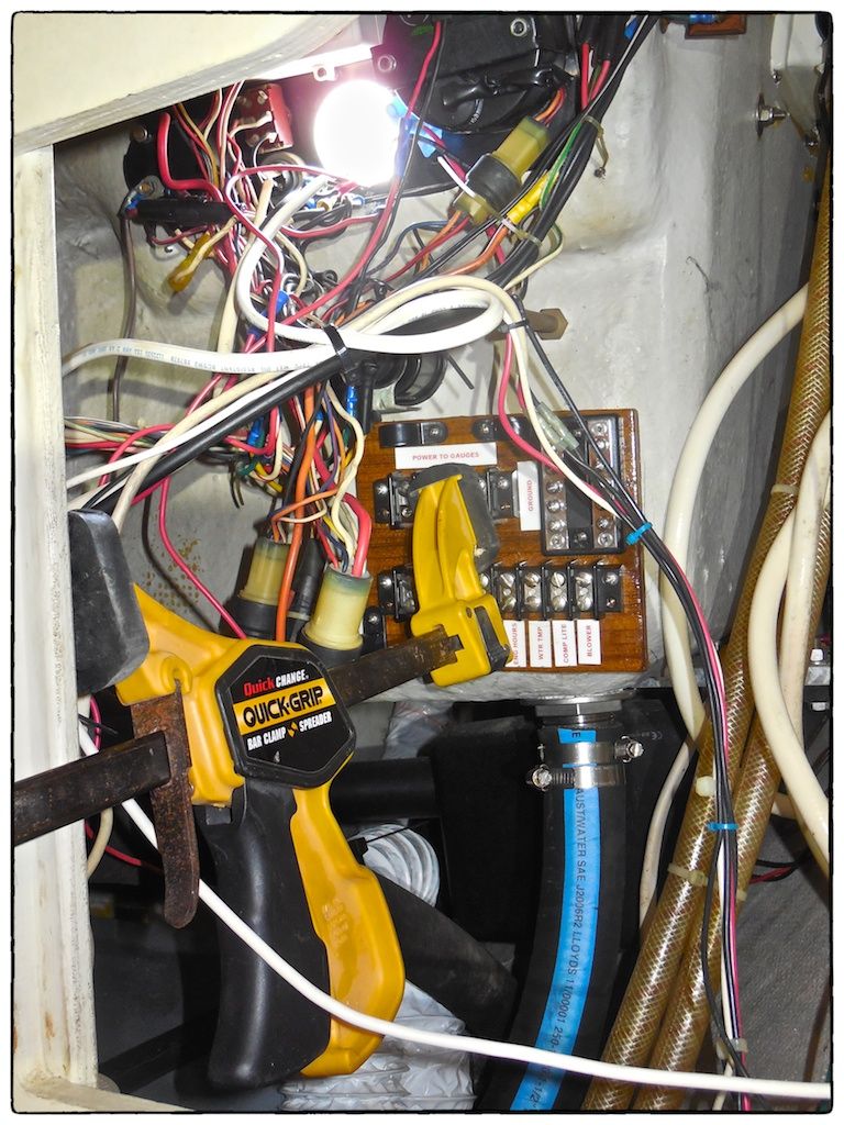 |
| I mixed up some epoxy and thickened it with #407 low-density fairing filler--it was the consistency of chunky peanut butter. I smeared the thickened epoxy on the back of the epoxy-coated teak panel and clamped it to the internal area of the fiberglass just below and outboard of the engine control panel. This work was done from inside the quarter berth looking aft. |
Checking the Old Gauges
While the epoxy was curing, I decided to check the operation of the old gauges the best I could and install the new red LED bulbs before reinstalling the gauges. The voltmeter and the water temperature gauge seemed to work fine.
 |
| After having it powered up directly to a 12-volt source for over an hour, the engine-hour meter didn't advance. So, what I assumed was a wiring problem was actually a gauge failure. |
Gauge Installation
The replacement of engine-hour meter and its relocation to the engine panel was accomplished easily. The power to it was fed from the ignition switch--so, whenever the ignition switch is on, it registers hours and tenths of hours.
As an extension of the auxiliary diesel tank project, a new fuel gauge had to be added to monitor the level in the auxiliary tank. I decided to buy two new fuel gauges and install them next to each other in the port cockpit coaming with the auxiliary tank's gauge below the primary tank's gauge. I had plastic labels made to keep from getting them mixed up. I reinstalled the existing voltmeter and water temperature gauge.
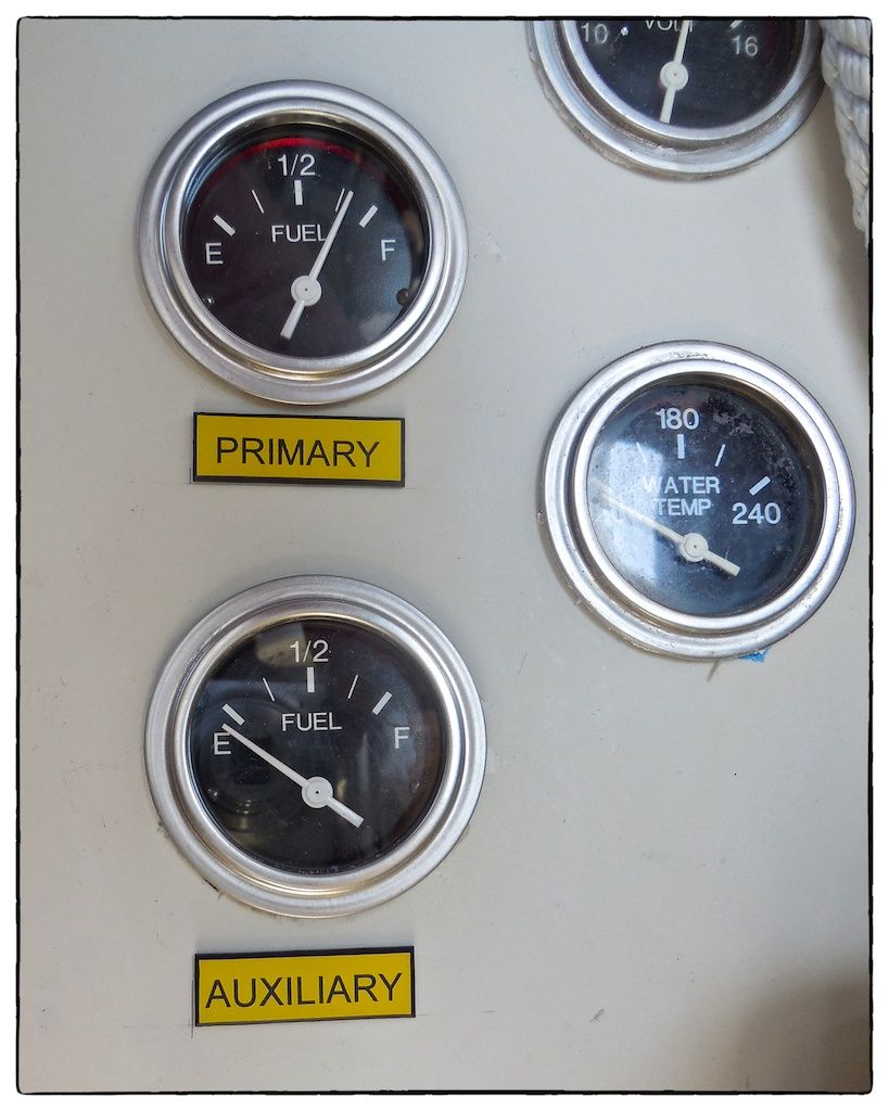
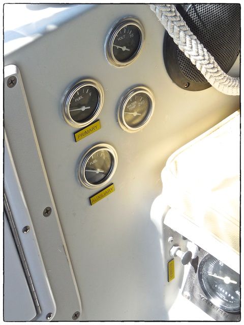 |
| This view of the new gauges is looking down from the helm seat. The yellow and black plastic labels made a nice finishing touch. |
 |
| The first step of the rewiring was to wire all the gauges to the new panel. Like the main electrical panel, all wires were labeled before fastening to the new terminal strip. |
A Functional Problem
After the new fuel gauges were completely wired, I checked the function of the gauges by simply turning the ignition switch on. As I turned on the ignition switch, the auxiliary fuel tank's gauge moved slightly in a positive direction but stayed below the "empty" mark--this tank was completely empty and the function appeared to be correct. To completely check the operation of the auxiliary tank's sender unit, I unbolted the sender's flange and pulled it out of the tank. While moving the arm on the sending unit, the fuel gauge changed accordingly. It was working perfectly.
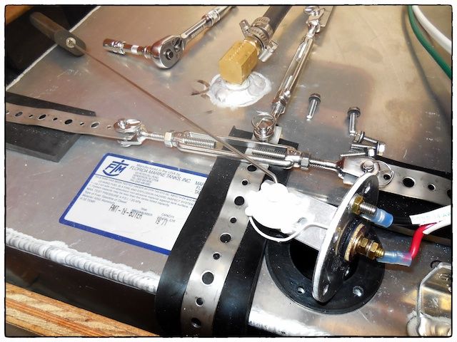 |
| To completely check the operation of the auxiliary tank's sender unit, I unbolted the flange and puller it out of the tank. This one worked perfectly. |
On the other hand, the primary fuel tank's gauge (which was wired identically) moved in a negative direction when energized. As a check, I temporarily hooked up the old fuel gauge and it did the same thing. The "below empty" reading indicated an open circuit in the sending unit. The resistance readings on the sending unit were erratic, many times an open circuit was indicated.
After spending a lot of time troubleshooting this one gauge malfunction, I determined that the sending unit inside the primary tank was the problem. So, I ordered a new sending unit and I'm waiting for it to arrive--I will append this blogpost when I install it.
Connecting New Engine Room Blower
I replaced the engine room blower and all the vent hoses last fall but I didn't connect the blower until I rewired the gauges. The blower is powered by the ignition and further controlled by a push/pull switch near the engine panel. This was a pretty simple rewiring task.
Summary
While I changed all the wiring to the gauges, the engine and engine control panel still contain a lot of old un-tinned wires. The replacement of the wiring between the engine and the instruments, as well as the general engine wiring, will be covered in Part 2.
For this first part of the project, I purchased the two new fuel gauges at half price--about $50 total. The new engine hour meter cost about $45, including shipping. Most of the other materials came from my stockpile of boat materials. Consequently, the total cost of this part of the project was about $125. This effort took two weekends to complete, mostly because of all the troubleshooting to get one fuel gauge to work--a typical boat project!
Thanks for following our blog!
After replacing the sender in the primary fuel tank, both fuel gauges are now working properly. The replacement sender was made by Moeller and purchased from Amazon. You can see a red glow from the new red LED instrument lights in the primary fuel gauge. (The auxiliary diesel tank is still empty.)
Addendum - April 11, 2014
After replacing the sender in the primary fuel tank, both fuel gauges are now working properly. The replacement sender was made by Moeller and purchased from Amazon. You can see a red glow from the new red LED instrument lights in the primary fuel gauge. (The auxiliary diesel tank is still empty.)
 |
| After replacing the sender in the primary fuel tank, both fuel gauges are now working! |
No comments:
Post a Comment